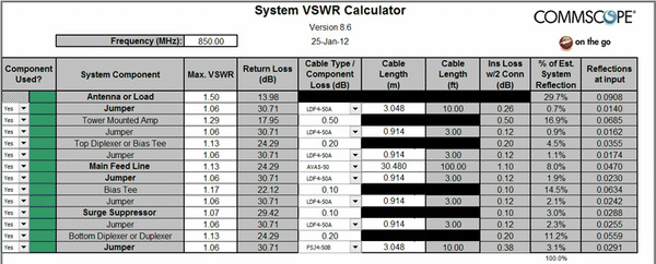
For many years in the cellular industry, the RF Path consisted of the shelter radio equipment, main transmission line, jumper cables and a tower-top antenna. Today’s cell sites are more complex, with additional devices such as tower mounted amplifiers and diplexers regularly installed. These additional devices introduce challenges when measuring network performance, particularly return loss.
Return loss is an engineering term for the loss of signal power when transmitting voice and data traffic in a wireless network. VSWR (Voltage Standing Wave Ratio) is a related term that has to do with how well the impedances of the antenna, radio and other RF Path equipment are matched. VSWR is the more commonly reported specification on product data sheets, but it can be converted into a return loss value. In modern test equipment, return loss is often preferred over VSWR since it provides better discrimination of accuracy at low VSWR values (e.g. a return loss of 22 dB would equate to a VSWR of 1.1726).
Operators care about return loss and VSWR as measurements of the efficiency in the RF Path. When complete RF Path measurements over a frequency band are performed at the bottom of the transmission line at a cell site, these are called return loss sweeps, or VSWR sweeps. If a sweep reports a 10 dB return loss, that means 10 percent of the power does not go through the RF Path to the antenna. A 20 dB return loss means only 1 percent of the power does not go through.
It is inevitable that some signal power will be lost at any cell site due to the nature of sending RF signals through components in the total RF Path. In years past, the antenna was by far the component with the highest possible VSWR impact. Out-of-specification VSWR sweeps conducted at the bottom of the transmission line could often be traced to an out-of-specification antenna. However, with more components added into wireless networks, the antenna is no longer the only major VSWR contributor in the RF Path.

Anyone conducting VSWR sweeps knows that calculating return loss is now more challenging with additional devices in the RF Path. To help in this effort, CommScope makes available on our website a System VSWR Calculator. The calculator is a spreadsheet that accepts VSWR specifications for all the components in your RF Path—tower mounted amplifiers, diplexers, bias tees, etc.—and calculates both the typical system return loss along with the worst case return loss. These multiple solutions are possible because each contributor is a vector having both amplitude and phase.
You will also notice in the System VSWR Calculator spreadsheet a second worksheet for calculating the entire system PIM (Passive Intermodulation). PIM is another important network measurement that can be challenging to calculate accurately in today’s complex networks. I will speak more about PIM and PIM measurement tools that CommScope offers in my next blog post.
Until then, does anyone have advice about making accurate VSWR sweeps and measuring return loss in wireless networks today? Has anyone tried the System VSWR Calculator and have feedback?


