HHT4-65B-R2
12-port, Dual Band, DualPol® Planar Array® Antenna, 4x 1850–1995 and 8x 2490-2690MHz, 65° HPBW, 2x internal RET.
Specifications
Features and Benefits
- 2 columns for 1895 MHz and 4 columns for 2490-2690 MHz
- Two internal RETs to control the antenna arrays
- Integrated with a calibration board
Specifications
General Specifications
| Antenna Type | Sector |
| Band | Multiband |
| Calibration Connector Interface | N Female |
| Calibration Connector Quantity | 1 |
| Color | Light Gray (RAL 7035) |
| Grounding Type | RF connector inner conductor and body grounded to reflector and mounting bracket |
| Performance Note | Outdoor usage |
| Radome Material | PVC, UV resistant |
| Radiator Material | Brass | Low loss circuit board |
| Reflector Material | Aluminum |
| RF Connector Interface | 4.1-9.5 DIN Female |
| RF Connector Location | Bottom |
| RF Connector Quantity, high band | 12 |
| RF Connector Quantity, total | 12 |
Remote Electrical Tilt (RET) Information
| RET Interface, quantity | 2 male |
| Input Voltage | 10–30 Vdc |
| Internal RET | High band (2) |
| Power Consumption, idle state, maximum | 1 W |
| Power Consumption, normal conditions, maximum | 13 W |
| Protocol | 3GPP/AISG 2.0 (Single RET) |
Dimensions
| Width | 320 mm | 12.598 in |
| Depth | 170 mm | 6.693 in |
| Length | 1820 mm | 71.654 in |
| Net Weight, without mounting kit | 24 kg | 52.911 lb |
| TDD Column Spacing | 75 mm | 2.953 in |
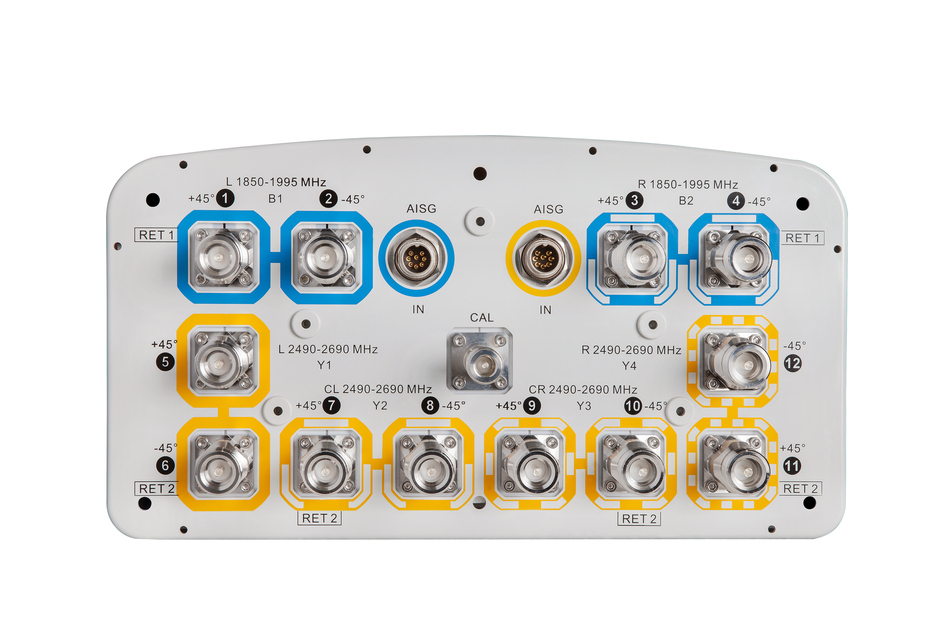
Port Configuration
| Click on image to enlarge. |

Electrical Specifications
| Impedance | 50 ohm |
| Operating Frequency Band | 1850 – 1995 MHz | 2490 – 2690 MHz |
| Polarization | ±45° |
Beam Forming Weights
| Click on image to enlarge. |

Electrical Specifications
| Frequency Band, MHz | 1850–1995 | 2490–2690 |
| Beam Tilt, degrees | 0–8 | 0–8 |
| Beam Tilt Tolerance, degrees | ±1 | ±1 |
| Coupling level, Amp, Antenna port to Cal port, dB | 26 | |
| Coupling level, max Amp Δ, Antenna port to Cal port, dB | ±2 | |
| Coupler, max Amp Δ, Antenna port to Cal port, dB | 0.9 | |
| Coupler, max Phase Δ, Antenna port to Cal port, degrees | 7 | |
| Isolation, Cross Polarization, dB | 25 | 25 |
| Isolation, Cross Polarization, port to port, dB | 25 | 25 |
| Isolation, Cross Polarization, port to port, between two columns, dB | 25 | 25 |
| VSWR | Return loss, dB | 1.5 | 14.0 | 1.5 | 14.0 |
| PIM, 3rd Order, 2 x 20 W, dBc | -153 | -146 |
Electrical Specifications, Broadcast 65
| Frequency Band, MHz | 1850–1995 | 2490–2690 |
| Gain, dBi | 17.0 | |
| Beamwidth, Horizontal, degrees | 65 | |
| Beamwidth, Horizontal Tolerance, degrees | ±5 | |
| Beamwidth, Vertical, degrees | 5.0 | |
| Beamwidth, Vertical Tolerance, degrees | ±0.5 | |
| CPR at Boresight, dB | 17 | |
| Front-to-Back Total Power at 180° ± 30°, dB | 27 | |
| Null Fill, dB | -22 | |
| USLS (First Lobe), dB | 18 |
Electrical Specifications, Service Beam
| Frequency Band, MHz | 1850–1995 | 2490–2690 |
| Steered 0° Gain, dBi | 22.5 | |
| Steered 0° Gain Tolerance, dBi | ±0.5 | |
| Steered 0° Beamwidth, Horizontal, degrees | 22 | |
| Steered 0° CPR at Beampeak, dB | 18 | |
| Steered 0° Front-to-Back Total Power at 180° ± 30°, dB | 30 | |
| Steered 0° Horizontal Sidelobe, dB | -10 | |
| Steered 30° Gain, dBi | 21.0 | |
| Steered 30° Gain Tolerance, dBi | ±0.5 |
Electrical Specifications, Single Column
| Frequency Band, MHz | 1850–1995 | 2490–2690 |
| Gain, dBi | 17.4 | 17.6 |
| Beamwidth, Horizontal, degrees | 64 | 70 |
| Beamwidth, Horizontal Tolerance, degrees | ±8 | ±8 |
| Beamwidth, Vertical, degrees | 5.4 | 4.1 |
| Beamwidth, Vertical Tolerance, degrees | ±0.5 | ±0.5 |
| CPR at Sector, dB | 10 | 10 |
| Front-to-Back Total Power at 180° ± 30°, dB | 30 | 25 |
| USLS (First Lobe), dB | 18 | 18 |
| Input Power per Port, maximum, watts | 300 | 25 |
Mechanical Specifications
| Wind Loading @ Velocity, maximum | 1,253.0 N @ 150 km/h (281.7 lbf @ 150 km/h) |
| Wind Speed, maximum | 250 km/h (155 mph) |
Packaging and Weights
| Width, packed | 427 mm | 16.811 in |
| Depth, packed | 304 mm | 11.969 in |
| Length, packed | 1931 mm | 76.024 in |
| Weight, gross | 36 kg | 79.366 lb |
Regulatory Compliance/Certifications
| Agency | Classification |
| ISO 9001:2015 | Designed, manufactured and/or distributed under this quality management system |
General Specifications
| Antenna Type | Sector |
| Band | Multiband |
| Calibration Connector Interface | N Female |
| Calibration Connector Quantity | 1 |
| Color | Light Gray (RAL 7035) |
| Grounding Type | RF connector inner conductor and body grounded to reflector and mounting bracket |
| Performance Note | Outdoor usage |
| Radome Material | PVC, UV resistant |
| Radiator Material | Brass | Low loss circuit board |
| Reflector Material | Aluminum |
| RF Connector Interface | 4.1-9.5 DIN Female |
| RF Connector Location | Bottom |
| RF Connector Quantity, high band | 12 |
| RF Connector Quantity, total | 12 |
Remote Electrical Tilt (RET) Information
| RET Interface, quantity | 2 male |
| Input Voltage | 10–30 Vdc |
| Internal RET | High band (2) |
| Power Consumption, idle state, maximum | 1 W |
| Power Consumption, normal conditions, maximum | 13 W |
| Protocol | 3GPP/AISG 2.0 (Single RET) |
Dimensions
| Width | 320 mm | 12.598 in |
| Depth | 170 mm | 6.693 in |
| Length | 1820 mm | 71.654 in |
| Net Weight, without mounting kit | 24 kg | 52.911 lb |
| TDD Column Spacing | 75 mm | 2.953 in |
Electrical Specifications
| Impedance | 50 ohm |
| Operating Frequency Band | 1850 – 1995 MHz | 2490 – 2690 MHz |
| Polarization | ±45° |
Electrical Specifications
| Frequency Band, MHz | 1850–1995 | 2490–2690 |
| Beam Tilt, degrees | 0–8 | 0–8 |
| Beam Tilt Tolerance, degrees | ±1 | ±1 |
| Coupling level, Amp, Antenna port to Cal port, dB | 26 | |
| Coupling level, max Amp Δ, Antenna port to Cal port, dB | ±2 | |
| Coupler, max Amp Δ, Antenna port to Cal port, dB | 0.9 | |
| Coupler, max Phase Δ, Antenna port to Cal port, degrees | 7 | |
| Isolation, Cross Polarization, dB | 25 | 25 |
| Isolation, Cross Polarization, port to port, dB | 25 | 25 |
| Isolation, Cross Polarization, port to port, between two columns, dB | 25 | 25 |
| VSWR | Return loss, dB | 1.5 | 14.0 | 1.5 | 14.0 |
| PIM, 3rd Order, 2 x 20 W, dBc | -153 | -146 |
Electrical Specifications, Broadcast 65
| Frequency Band, MHz | 1850–1995 | 2490–2690 |
| Gain, dBi | 17.0 | |
| Beamwidth, Horizontal, degrees | 65 | |
| Beamwidth, Horizontal Tolerance, degrees | ±5 | |
| Beamwidth, Vertical, degrees | 5.0 | |
| Beamwidth, Vertical Tolerance, degrees | ±0.5 | |
| CPR at Boresight, dB | 17 | |
| Front-to-Back Total Power at 180° ± 30°, dB | 27 | |
| Null Fill, dB | -22 | |
| USLS (First Lobe), dB | 18 |
Electrical Specifications, Service Beam
| Frequency Band, MHz | 1850–1995 | 2490–2690 |
| Steered 0° Gain, dBi | 22.5 | |
| Steered 0° Gain Tolerance, dBi | ±0.5 | |
| Steered 0° Beamwidth, Horizontal, degrees | 22 | |
| Steered 0° CPR at Beampeak, dB | 18 | |
| Steered 0° Front-to-Back Total Power at 180° ± 30°, dB | 30 | |
| Steered 0° Horizontal Sidelobe, dB | -10 | |
| Steered 30° Gain, dBi | 21.0 | |
| Steered 30° Gain Tolerance, dBi | ±0.5 |
Electrical Specifications, Single Column
| Frequency Band, MHz | 1850–1995 | 2490–2690 |
| Gain, dBi | 17.4 | 17.6 |
| Beamwidth, Horizontal, degrees | 64 | 70 |
| Beamwidth, Horizontal Tolerance, degrees | ±8 | ±8 |
| Beamwidth, Vertical, degrees | 5.4 | 4.1 |
| Beamwidth, Vertical Tolerance, degrees | ±0.5 | ±0.5 |
| CPR at Sector, dB | 10 | 10 |
| Front-to-Back Total Power at 180° ± 30°, dB | 30 | 25 |
| USLS (First Lobe), dB | 18 | 18 |
| Input Power per Port, maximum, watts | 300 | 25 |
Mechanical Specifications
| Wind Loading @ Velocity, maximum | 1,253.0 N @ 150 km/h (281.7 lbf @ 150 km/h) |
| Wind Speed, maximum | 250 km/h (155 mph) |
Packaging and Weights
| Width, packed | 427 mm | 16.811 in |
| Depth, packed | 304 mm | 11.969 in |
| Length, packed | 1931 mm | 76.024 in |
| Weight, gross | 36 kg | 79.366 lb |
| Click on image to enlarge. |
| Click on image to enlarge. |
Regulatory Compliance/Certifications
| Agency | Classification |
| ISO 9001:2015 | Designed, manufactured and/or distributed under this quality management system |
Documentation & Downloads
Assembly Drawing
Product Information
Product Specification
Warranty
Assembly Drawing
Product Compliance Documentation
Product Information
Product Specification
Warranty
Related Products and Accessories
Included Products
Antennas
-
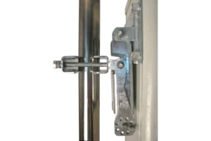
![]() BSAMNT-3 Wide Profile Antenna Downtilt Mounting Kit for 2.4 - 4.5 in (60 - 115 mm) OD round members. Kit contains one scissor top bracket set and one bottom bracket set.
BSAMNT-3 Wide Profile Antenna Downtilt Mounting Kit for 2.4 - 4.5 in (60 - 115 mm) OD round members. Kit contains one scissor top bracket set and one bottom bracket set.
Structural Support, Tools & Accessories
-
![]() BSAMNT-3 Wide Profile Antenna Downtilt Mounting Kit for 2.4 - 4.5 in (60 - 115 mm) OD round members. Kit contains one scissor top bracket set and one bottom bracket set.
BSAMNT-3 Wide Profile Antenna Downtilt Mounting Kit for 2.4 - 4.5 in (60 - 115 mm) OD round members. Kit contains one scissor top bracket set and one bottom bracket set.
Related Products
Antennas
-
![]() APS-XT Antenna Orientation and Location Sensing System
APS-XT Antenna Orientation and Location Sensing System
Included Products
Antennas
-
![]() BSAMNT-3 Wide Profile Antenna Downtilt Mounting Kit for 2.4 - 4.5 in (60 - 115 mm) OD round members. Kit contains one scissor top bracket set and one bottom bracket set.
BSAMNT-3 Wide Profile Antenna Downtilt Mounting Kit for 2.4 - 4.5 in (60 - 115 mm) OD round members. Kit contains one scissor top bracket set and one bottom bracket set.
Structural Support, Tools & Accessories
-
![]() BSAMNT-3 Wide Profile Antenna Downtilt Mounting Kit for 2.4 - 4.5 in (60 - 115 mm) OD round members. Kit contains one scissor top bracket set and one bottom bracket set.
BSAMNT-3 Wide Profile Antenna Downtilt Mounting Kit for 2.4 - 4.5 in (60 - 115 mm) OD round members. Kit contains one scissor top bracket set and one bottom bracket set.
-
![]() BSAMNT-3 Wide Profile Antenna Downtilt Mounting Kit for 2.4 - 4.5 in (60 - 115 mm) OD round members. Kit contains one scissor top bracket set and one bottom bracket set.
BSAMNT-3 Wide Profile Antenna Downtilt Mounting Kit for 2.4 - 4.5 in (60 - 115 mm) OD round members. Kit contains one scissor top bracket set and one bottom bracket set.
Related Products
Antennas
-
![]() APS-XT Antenna Orientation and Location Sensing System
APS-XT Antenna Orientation and Location Sensing System
Other Ways to Browse
