RVVS4-65S-R3
14-port sector antenna, 2x 698-960(R1), 4x 1695-2690(Y1&Y2) MHz, 65° HPBW and 8x 3300-3800(P1) MHz, 90° HPBW, 4x RET.
Features and Benefits
- All Internal RET actuators are connected in “Cascaded SRET” configuration
- M-LOC cluster connector for 3.3-3.8GHz, equipped with calibration port
- Combination of FDD MIMO antenna and 3.5GHz 8T8R TDD beam forming antenna, all in one for 5G ready
Specifications
General Specifications
| Antenna Type | Sector- and beamforming |
| Band | Multiband |
| Calibration Connector Interface | M-LOC |
| Calibration Connector Quantity | 1 |
| Color | Light Gray (RAL 7035) |
| Grounding Type | RF connector inner conductor and body grounded to reflector and mounting bracket |
| Performance Note | Outdoor usage |
| Radome Material | Fiberglass, UV resistant |
| Reflector Material | Aluminum |
| RF Connector Interface | 4.3-10 Female | M-LOC |
| RF Connector Location | Bottom |
| RF Connector Quantity, high band | 8 |
| RF Connector Quantity, mid band | 4 |
| RF Connector Quantity, low band | 2 |
| RF Connector Quantity, total | 14 |
Remote Electrical Tilt (RET) Information
| RET Hardware | CommRET v2 |
| RET Interface | 8-pin DIN Female | 8-pin DIN Male |
| RET Interface, quantity | 1 female | 1 male |
| Input Voltage | 10–30 Vdc |
| Internal RET | High band (1) | Mid band (2) |
| Power Consumption, active state, maximum | 10 W |
| Power Consumption, idle state, maximum | 2 W |
| Protocol | 3GPP/AISG 2.0 |
Dimensions
| Width | 395 mm | 15.551 in |
| Depth | 228 mm | 8.976 in |
| Length | 800 mm | 31.496 in |
| Net Weight, antenna only | 16.6 kg | 36.597 lb |
Array Layout
| Click on image to enlarge. |

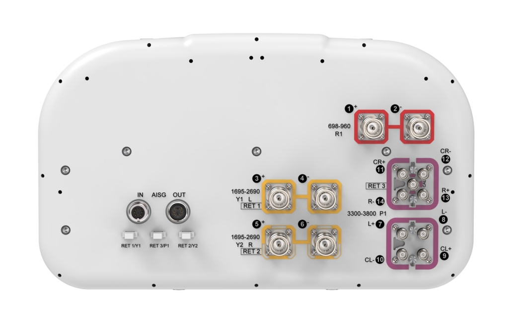
Port Configuration
| Click on image to enlarge. |

Electrical Specifications
| Impedance | 50 ohm |
| Operating Frequency Band | 698 – 960 MHz | 1695 – 2690 MHz | 3300 – 3800 MHz |
| Polarization | ±45° |
| Total Input Power, maximum | 800 W @ 50 °C |
Electrical Specifications
| R1 | R1 | Y1,Y2 | Y1,Y2 | Y1,Y2 | P1 | P1 | |
| Frequency Band, MHz | 698–862 | 880–960 | 1695–1920 | 1920–2200 | 2300–2690 | 3300–3600 | 3600–3800 |
| RF Port | 1,2 | 1,2 | 3-6 | 3-6 | 3-6 | 7-14 | 7-14 |
| Beamwidth, Horizontal, degrees | 70 | 68 | 70 | 71 | 63 | 81 | 74 |
| Beamwidth, Vertical, degrees | 27.7 | 22.8 | 13.2 | 12 | 10.3 | 7.2 | 6.8 |
| Beam Tilt, degrees | 12 | 12 | 2–12 | 2–12 | 2–12 | 0–10 | 0–10 |
| USLS (First Lobe), dB | 14 | 13 | 16 | 15 | 15 | 15 | 14 |
| Front-to-Back Ratio at 180°, dB | 32 | 33 | 33 | 34 | 31 | 29 | 29 |
| Front-to-Back Total Power at 180° ± 30°, dB | 21 | 22 | 26 | 28 | 27 | 20 | 22 |
| Coupling level, Amp, Antenna port to Cal port, dB | -26 | -26 | |||||
| Coupling level, max Amp Δ, Antenna port to Cal port, dB | ±2 | ±2 | |||||
| Coupler, max Amp Δ, Antenna port to Cal port, dB | 0.9 | 0.9 | |||||
| Coupler, max Phase Δ, Antenna port to Cal port, degrees | 7 | 7 | |||||
| CPR at Boresight, dB | 20 | 23 | 22 | 24 | 19 | 14 | 15 |
| CPR at Sector, dB | 10 | 10 | 15 | 11 | 8 | 7 | 6 |
| Isolation, Cross Polarization, dB | 25 | 25 | 25 | 25 | 25 | 25 | 25 |
| Isolation, Inter-band, dB | 25 | 25 | 25 | 25 | 25 | 25 | 25 |
| Isolation, Co-polarization, dB | 20 | 20 | |||||
| VSWR | Return loss, dB | 1.5 | 14.0 | 1.5 | 14.0 | 1.5 | 14.0 | 1.5 | 14.0 | 1.5 | 14.0 | 1.5 | 14.0 | 1.5 | 14.0 |
| PIM, 3rd Order, 2 x 20 W, dBc | -150 | -150 | -150 | -150 | -150 | -140 | -140 |
| Input Power per Port at 50°C, maximum, watts | 200 | 200 | 200 | 200 | 150 | 75 | 75 |
Electrical Specifications, BASTA
| Frequency Band, MHz | 698–862 | 880–960 | 1695–1920 | 1920–2200 | 2300–2690 | 3300–3600 | 3600–3800 |
| Gain by all Beam Tilts, average, dBi | 11.5 | 11.7 | 14.1 | 14.3 | 15.0 | 14.3 | 14.7 |
| Gain by all Beam Tilts Tolerance, dB | ±0.5 | ±0.4 | ±0.5 | ±0.5 | ±0.6 | ±1.4 | ±1.2 |
| Beamwidth, Horizontal Tolerance, degrees | ±2.2 | ±2.3 | ±4.4 | ±4.6 | ±6.6 | ±31.8 | ±20.3 |
| Beamwidth, Vertical Tolerance, degrees | ±3.3 | ±2.1 | ±0.9 | ±0.9 | ±0.8 | ±0.9 | ±0.8 |
| USLS, beampeak to 20° above beampeak, dB | 16 | 15 | 15 | 14 | 12 |
Electrical Specifications, Broadcast 65
| Frequency Band, MHz | 698–862 | 880–960 | 1695–1920 | 1920–2200 | 2300–2690 | 3300–3600 | 3600–3800 |
| Gain, dBi | 17.6 | 17.8 | |||||
| Beamwidth, Horizontal, degrees | 65 | 65 | |||||
| Beamwidth, Vertical, degrees | 7.1 | 6.6 | |||||
| Front-to-Back Total Power at 180° ± 30°, dB | 26 | 28 | |||||
| USLS (First Lobe), dB | 19 | 17 |
Electrical Specifications, Envelope Pattern
| Frequency Band, MHz | 698–862 | 880–960 | 1695–1920 | 1920–2200 | 2300–2690 | 3300–3600 | 3600–3800 |
| Gain, dBi | 19.5 | 19.7 | |||||
| Beamwidth, Horizontal at 10 dB, degrees | 119 | 111 | |||||
| Front-to-Back Total Power at 180° ± 30°, dB | 26 | 28 | |||||
| USLS (First Lobe), dB | 19 | 19 |
Electrical Specifications, Service Beam
| Frequency Band, MHz | 698–862 | 880–960 | 1695–1920 | 1920–2200 | 2300–2690 | 3300–3600 | 3600–3800 |
| Steered 0° Gain, dBi | 19.5 | 19.7 | |||||
| Steered 0° Beamwidth, Horizontal, degrees | 24 | 22 | |||||
| Steered 0° Front-to-Back Total Power at 180° ± 30°, dB | 29 | 30 | |||||
| Steered 0° Horizontal Sidelobe, dB | 13 | 13 | |||||
| Steered 30° Gain, dBi | 18.2 | 18.9 | |||||
| Steered 30° Beamwidth, Horizontal, degrees | 29 | 26 | |||||
| Steered 30° Front-to-Back Total Power at 180° ± 30°, dB | 27 | 28 |
Mechanical Specifications
| Wind Loading @ Velocity, frontal | 110.0 N @ 150 km/h (24.7 lbf @ 150 km/h) |
| Wind Loading @ Velocity, lateral | 93.0 N @ 150 km/h (20.9 lbf @ 150 km/h) |
| Wind Loading @ Velocity, maximum | 220.0 N @ 150 km/h (49.5 lbf @ 150 km/h) |
| Wind Loading @ Velocity, rear | 126.0 N @ 150 km/h (28.3 lbf @ 150 km/h) |
| Wind Speed, maximum | 241 km/h (150 mph) |
Packaging and Weights
| Width, packed | 509 mm | 20.039 in |
| Depth, packed | 386 mm | 15.197 in |
| Length, packed | 941 mm | 37.047 in |
| Weight, gross | 26.1 kg | 57.541 lb |
Regulatory Compliance/Certifications
| Agency | Classification |
| ISO 9001:2015 | Designed, manufactured and/or distributed under this quality management system |
General Specifications
| Antenna Type | Sector- and beamforming |
| Band | Multiband |
| Calibration Connector Interface | M-LOC |
| Calibration Connector Quantity | 1 |
| Color | Light Gray (RAL 7035) |
| Grounding Type | RF connector inner conductor and body grounded to reflector and mounting bracket |
| Performance Note | Outdoor usage |
| Radome Material | Fiberglass, UV resistant |
| Reflector Material | Aluminum |
| RF Connector Interface | 4.3-10 Female | M-LOC |
| RF Connector Location | Bottom |
| RF Connector Quantity, high band | 8 |
| RF Connector Quantity, mid band | 4 |
| RF Connector Quantity, low band | 2 |
| RF Connector Quantity, total | 14 |
Remote Electrical Tilt (RET) Information
| RET Hardware | CommRET v2 |
| RET Interface | 8-pin DIN Female | 8-pin DIN Male |
| RET Interface, quantity | 1 female | 1 male |
| Input Voltage | 10–30 Vdc |
| Internal RET | High band (1) | Mid band (2) |
| Power Consumption, active state, maximum | 10 W |
| Power Consumption, idle state, maximum | 2 W |
| Protocol | 3GPP/AISG 2.0 |
Dimensions
| Width | 395 mm | 15.551 in |
| Depth | 228 mm | 8.976 in |
| Length | 800 mm | 31.496 in |
| Net Weight, antenna only | 16.6 kg | 36.597 lb |
Electrical Specifications
| Impedance | 50 ohm |
| Operating Frequency Band | 698 – 960 MHz | 1695 – 2690 MHz | 3300 – 3800 MHz |
| Polarization | ±45° |
| Total Input Power, maximum | 800 W @ 50 °C |
Electrical Specifications
| R1 | R1 | Y1,Y2 | Y1,Y2 | Y1,Y2 | P1 | P1 | |
| Frequency Band, MHz | 698–862 | 880–960 | 1695–1920 | 1920–2200 | 2300–2690 | 3300–3600 | 3600–3800 |
| RF Port | 1,2 | 1,2 | 3-6 | 3-6 | 3-6 | 7-14 | 7-14 |
| Beamwidth, Horizontal, degrees | 70 | 68 | 70 | 71 | 63 | 81 | 74 |
| Beamwidth, Vertical, degrees | 27.7 | 22.8 | 13.2 | 12 | 10.3 | 7.2 | 6.8 |
| Beam Tilt, degrees | 12 | 12 | 2–12 | 2–12 | 2–12 | 0–10 | 0–10 |
| USLS (First Lobe), dB | 14 | 13 | 16 | 15 | 15 | 15 | 14 |
| Front-to-Back Ratio at 180°, dB | 32 | 33 | 33 | 34 | 31 | 29 | 29 |
| Front-to-Back Total Power at 180° ± 30°, dB | 21 | 22 | 26 | 28 | 27 | 20 | 22 |
| Coupling level, Amp, Antenna port to Cal port, dB | -26 | -26 | |||||
| Coupling level, max Amp Δ, Antenna port to Cal port, dB | ±2 | ±2 | |||||
| Coupler, max Amp Δ, Antenna port to Cal port, dB | 0.9 | 0.9 | |||||
| Coupler, max Phase Δ, Antenna port to Cal port, degrees | 7 | 7 | |||||
| CPR at Boresight, dB | 20 | 23 | 22 | 24 | 19 | 14 | 15 |
| CPR at Sector, dB | 10 | 10 | 15 | 11 | 8 | 7 | 6 |
| Isolation, Cross Polarization, dB | 25 | 25 | 25 | 25 | 25 | 25 | 25 |
| Isolation, Inter-band, dB | 25 | 25 | 25 | 25 | 25 | 25 | 25 |
| Isolation, Co-polarization, dB | 20 | 20 | |||||
| VSWR | Return loss, dB | 1.5 | 14.0 | 1.5 | 14.0 | 1.5 | 14.0 | 1.5 | 14.0 | 1.5 | 14.0 | 1.5 | 14.0 | 1.5 | 14.0 |
| PIM, 3rd Order, 2 x 20 W, dBc | -150 | -150 | -150 | -150 | -150 | -140 | -140 |
| Input Power per Port at 50°C, maximum, watts | 200 | 200 | 200 | 200 | 150 | 75 | 75 |
Electrical Specifications, BASTA
| Frequency Band, MHz | 698–862 | 880–960 | 1695–1920 | 1920–2200 | 2300–2690 | 3300–3600 | 3600–3800 |
| Gain by all Beam Tilts, average, dBi | 11.5 | 11.7 | 14.1 | 14.3 | 15.0 | 14.3 | 14.7 |
| Gain by all Beam Tilts Tolerance, dB | ±0.5 | ±0.4 | ±0.5 | ±0.5 | ±0.6 | ±1.4 | ±1.2 |
| Beamwidth, Horizontal Tolerance, degrees | ±2.2 | ±2.3 | ±4.4 | ±4.6 | ±6.6 | ±31.8 | ±20.3 |
| Beamwidth, Vertical Tolerance, degrees | ±3.3 | ±2.1 | ±0.9 | ±0.9 | ±0.8 | ±0.9 | ±0.8 |
| USLS, beampeak to 20° above beampeak, dB | 16 | 15 | 15 | 14 | 12 |
Electrical Specifications, Broadcast 65
| Frequency Band, MHz | 698–862 | 880–960 | 1695–1920 | 1920–2200 | 2300–2690 | 3300–3600 | 3600–3800 |
| Gain, dBi | 17.6 | 17.8 | |||||
| Beamwidth, Horizontal, degrees | 65 | 65 | |||||
| Beamwidth, Vertical, degrees | 7.1 | 6.6 | |||||
| Front-to-Back Total Power at 180° ± 30°, dB | 26 | 28 | |||||
| USLS (First Lobe), dB | 19 | 17 |
Electrical Specifications, Envelope Pattern
| Frequency Band, MHz | 698–862 | 880–960 | 1695–1920 | 1920–2200 | 2300–2690 | 3300–3600 | 3600–3800 |
| Gain, dBi | 19.5 | 19.7 | |||||
| Beamwidth, Horizontal at 10 dB, degrees | 119 | 111 | |||||
| Front-to-Back Total Power at 180° ± 30°, dB | 26 | 28 | |||||
| USLS (First Lobe), dB | 19 | 19 |
Electrical Specifications, Service Beam
| Frequency Band, MHz | 698–862 | 880–960 | 1695–1920 | 1920–2200 | 2300–2690 | 3300–3600 | 3600–3800 |
| Steered 0° Gain, dBi | 19.5 | 19.7 | |||||
| Steered 0° Beamwidth, Horizontal, degrees | 24 | 22 | |||||
| Steered 0° Front-to-Back Total Power at 180° ± 30°, dB | 29 | 30 | |||||
| Steered 0° Horizontal Sidelobe, dB | 13 | 13 | |||||
| Steered 30° Gain, dBi | 18.2 | 18.9 | |||||
| Steered 30° Beamwidth, Horizontal, degrees | 29 | 26 | |||||
| Steered 30° Front-to-Back Total Power at 180° ± 30°, dB | 27 | 28 |
Mechanical Specifications
| Wind Loading @ Velocity, frontal | 110.0 N @ 150 km/h (24.7 lbf @ 150 km/h) |
| Wind Loading @ Velocity, lateral | 93.0 N @ 150 km/h (20.9 lbf @ 150 km/h) |
| Wind Loading @ Velocity, maximum | 220.0 N @ 150 km/h (49.5 lbf @ 150 km/h) |
| Wind Loading @ Velocity, rear | 126.0 N @ 150 km/h (28.3 lbf @ 150 km/h) |
| Wind Speed, maximum | 241 km/h (150 mph) |
Packaging and Weights
| Width, packed | 509 mm | 20.039 in |
| Depth, packed | 386 mm | 15.197 in |
| Length, packed | 941 mm | 37.047 in |
| Weight, gross | 26.1 kg | 57.541 lb |
| Click on image to enlarge. |
| Click on image to enlarge. |
Regulatory Compliance/Certifications
| Agency | Classification |
| ISO 9001:2015 | Designed, manufactured and/or distributed under this quality management system |
Documentation & Downloads
Assembly Drawing
Installation Instruction
Product Information
Product Specification
Warranty
Assembly Drawing
Installation Instruction
Product Compliance Documentation
Product Information
Product Specification
Warranty
Related Products and Accessories
Included Products
Antennas
-
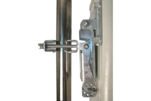
![]() BSAMNT-3 Wide Profile Antenna Downtilt Mounting Kit for 2.4 - 4.5 in (60 - 115 mm) OD round members. Kit contains one scissor top bracket set and one bottom bracket set.
BSAMNT-3 Wide Profile Antenna Downtilt Mounting Kit for 2.4 - 4.5 in (60 - 115 mm) OD round members. Kit contains one scissor top bracket set and one bottom bracket set.
Structural Support, Tools & Accessories
-
![]() BSAMNT-3 Wide Profile Antenna Downtilt Mounting Kit for 2.4 - 4.5 in (60 - 115 mm) OD round members. Kit contains one scissor top bracket set and one bottom bracket set.
BSAMNT-3 Wide Profile Antenna Downtilt Mounting Kit for 2.4 - 4.5 in (60 - 115 mm) OD round members. Kit contains one scissor top bracket set and one bottom bracket set.
Included Products
Antennas
-
![]() BSAMNT-3 Wide Profile Antenna Downtilt Mounting Kit for 2.4 - 4.5 in (60 - 115 mm) OD round members. Kit contains one scissor top bracket set and one bottom bracket set.
BSAMNT-3 Wide Profile Antenna Downtilt Mounting Kit for 2.4 - 4.5 in (60 - 115 mm) OD round members. Kit contains one scissor top bracket set and one bottom bracket set.
Structural Support, Tools & Accessories
-
![]() BSAMNT-3 Wide Profile Antenna Downtilt Mounting Kit for 2.4 - 4.5 in (60 - 115 mm) OD round members. Kit contains one scissor top bracket set and one bottom bracket set.
BSAMNT-3 Wide Profile Antenna Downtilt Mounting Kit for 2.4 - 4.5 in (60 - 115 mm) OD round members. Kit contains one scissor top bracket set and one bottom bracket set.
-
![]() BSAMNT-3 Wide Profile Antenna Downtilt Mounting Kit for 2.4 - 4.5 in (60 - 115 mm) OD round members. Kit contains one scissor top bracket set and one bottom bracket set.
BSAMNT-3 Wide Profile Antenna Downtilt Mounting Kit for 2.4 - 4.5 in (60 - 115 mm) OD round members. Kit contains one scissor top bracket set and one bottom bracket set.
Other Ways to Browse
