L4TNF-PSA
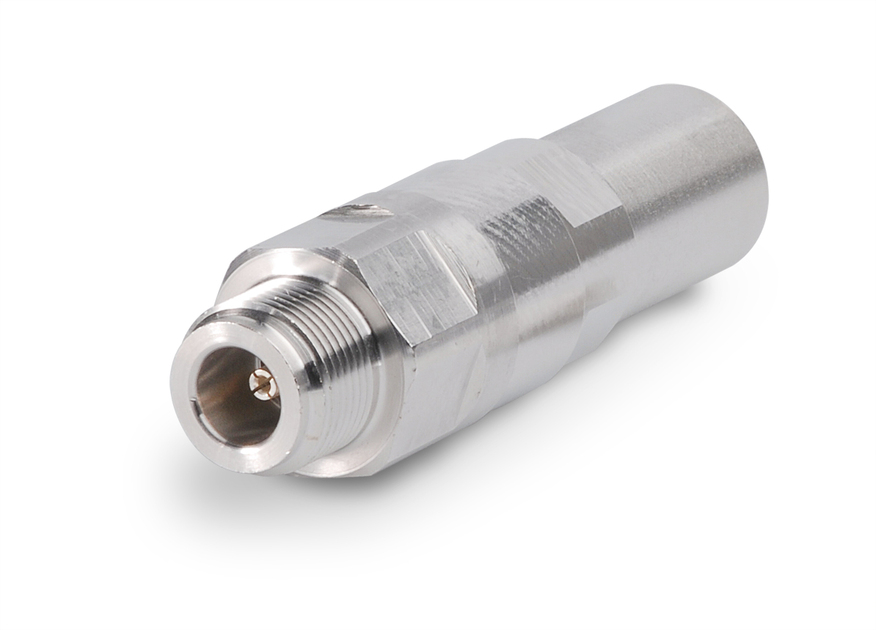
Type N Female Positive Stop™ for 1/2 in AL4RPV-50, LDF4-50A, HL4RPV-50 cable
Specifications
Product Classification
| Product Type | Wireless and radiating connector |
| Product Brand | HELIAX® | Positive Stop™ |
| Product Series | LDF4-50A |
| Ordering Note | CommScope® standard product (Global) |
General Specifications
| Body Style | Straight |
| Cable Family | AL4-50 |
| Harmonized System (HS) Code | 85366910 (Coaxial cable and other coaxial electric conductors) |
| Inner Contact Attachment Method | Captivated |
| Inner Contact Plating | Silver |
| Interface | N Female |
| Mounting Angle | Straight |
| Outer Contact Attachment Method | Ring-flare |
| Outer Contact Plating | Trimetal |
Dimensions
| Length | 73.66 mm | 2.900 in |
| Diameter | 22.35 mm | 0.880 in |
| Nominal Size | 1/2 in |
Outline Drawing
| Click on image to enlarge. |
Electrical Specifications
| 3rd Order IMD at Frequency | -116 dBm @ 910 MHz |
| 3rd Order IMD Test Method | Two +43 dBm carriers |
| Insertion Loss Coefficient, typical | 0.05 |
| Average Power at Frequency | 0.6 kW @ 900 MHz |
| Cable Impedance | 50 ohm |
| Connector Impedance | 50 ohm |
| dc Test Voltage | 2500 V |
| Inner Contact Resistance, maximum | 1 mOhm |
| Insulation Resistance, minimum | 5000 mOhm |
| Operating Frequency Band | 0 – 8800 MHz |
| Outer Contact Resistance, maximum | 0.25 mOhm |
| Peak Power, maximum | 10 kW |
| RF Operating Voltage, maximum (vrms) | 707 V |
| Shielding Effectiveness | -130 dB |
Return Loss/VSWR
| Frequency Band | VSWR | Return Loss (dB) |
| 50–1000 MHz | 1.023 | 38.89 |
| 1010–2200 MHz | 1.029 | 36.90 |
| 2210–3000 MHz | 1.046 | 32.96 |
| 3010–4000 MHz | 1.074 | 28.95 |
| 4010–6000 MHz | 1.119 | 25.01 |
Mechanical Specifications
| Attachment Durability | 25 cycles |
| Connector Retention Tensile Force | 889.64 N | 200.000 lbf |
| Connector Retention Torque | 5.42 N-m | 47.998 in lb |
| Insertion Force | 66.72 N | 15.000 lbf |
| Insertion Force Method | MIL-C-39012C-3.12, 4.6.9 |
| Interface Durability | 500 cycles |
| Interface Durability Method | IEC 61169-16:9.5 |
| Mechanical Shock Test Method | MIL-STD-202, Method 213, Test Condition I |
Environmental Specifications
| Operating Temperature | -55 °C to +85 °C (-67 °F to +185 °F) |
| Storage Temperature | -55 °C to +85 °C (-67 °F to +185 °F) |
| Corrosion Test Method | MIL-STD-1344A, Method 1001.1, Test Condition A |
| Immersion Depth | 1 m |
| Immersion Test Mating | Unmated |
| Immersion Test Method | IEC 60529:2001, IP68 |
| Moisture Resistance Test Method | MIL-STD-202F, Method 106F |
| Thermal Shock Test Method | MIL-STD-202F, Method 107G, Test Condition A-1, Low Temperature -55 °C |
| Vibration Test Method | IEC 60068-2-6 |
| Water Jetting Test Mating | Unmated |
| Water Jetting Test Method | IEC 60529:2001, IP66 |
Packaging and Weights
| Weight, net | 88.46 g | 0.195 lb |
Regulatory Compliance/Certifications
| Agency | Classification |
| ISO 9001:2015 | Designed, manufactured and/or distributed under this quality management system |
| ROHS | Compliant/Exempted |
|
CHINA-ROHS
|
Above maximum concentration value |
| UK-ROHS | Compliant/Exempted |
Product Classification
| Product Type | Wireless and radiating connector |
| Product Brand | HELIAX® | Positive Stop™ |
| Product Series | LDF4-50A |
| Ordering Note | CommScope® standard product (Global) |
General Specifications
| Body Style | Straight |
| Cable Family | AL4-50 |
| Harmonized System (HS) Code | 85366910 (Coaxial cable and other coaxial electric conductors) |
| Inner Contact Attachment Method | Captivated |
| Inner Contact Plating | Silver |
| Interface | N Female |
| Mounting Angle | Straight |
| Outer Contact Attachment Method | Ring-flare |
| Outer Contact Plating | Trimetal |
Dimensions
| Length | 73.66 mm | 2.900 in |
| Diameter | 22.35 mm | 0.880 in |
| Nominal Size | 1/2 in |
Electrical Specifications
| 3rd Order IMD at Frequency | -116 dBm @ 910 MHz |
| 3rd Order IMD Test Method | Two +43 dBm carriers |
| Insertion Loss Coefficient, typical | 0.05 |
| Average Power at Frequency | 0.6 kW @ 900 MHz |
| Cable Impedance | 50 ohm |
| Connector Impedance | 50 ohm |
| dc Test Voltage | 2500 V |
| Inner Contact Resistance, maximum | 1 mOhm |
| Insulation Resistance, minimum | 5000 mOhm |
| Operating Frequency Band | 0 – 8800 MHz |
| Outer Contact Resistance, maximum | 0.25 mOhm |
| Peak Power, maximum | 10 kW |
| RF Operating Voltage, maximum (vrms) | 707 V |
| Shielding Effectiveness | -130 dB |
Return Loss/VSWR
| Frequency Band | VSWR | Return Loss (dB) |
| 50–1000 MHz | 1.023 | 38.89 |
| 1010–2200 MHz | 1.029 | 36.90 |
| 2210–3000 MHz | 1.046 | 32.96 |
| 3010–4000 MHz | 1.074 | 28.95 |
| 4010–6000 MHz | 1.119 | 25.01 |
Mechanical Specifications
| Attachment Durability | 25 cycles |
| Connector Retention Tensile Force | 889.64 N | 200.000 lbf |
| Connector Retention Torque | 5.42 N-m | 47.998 in lb |
| Insertion Force | 66.72 N | 15.000 lbf |
| Insertion Force Method | MIL-C-39012C-3.12, 4.6.9 |
| Interface Durability | 500 cycles |
| Interface Durability Method | IEC 61169-16:9.5 |
| Mechanical Shock Test Method | MIL-STD-202, Method 213, Test Condition I |
Environmental Specifications
| Operating Temperature | -55 °C to +85 °C (-67 °F to +185 °F) |
| Storage Temperature | -55 °C to +85 °C (-67 °F to +185 °F) |
| Corrosion Test Method | MIL-STD-1344A, Method 1001.1, Test Condition A |
| Immersion Depth | 1 m |
| Immersion Test Mating | Unmated |
| Immersion Test Method | IEC 60529:2001, IP68 |
| Moisture Resistance Test Method | MIL-STD-202F, Method 106F |
| Thermal Shock Test Method | MIL-STD-202F, Method 107G, Test Condition A-1, Low Temperature -55 °C |
| Vibration Test Method | IEC 60068-2-6 |
| Water Jetting Test Mating | Unmated |
| Water Jetting Test Method | IEC 60529:2001, IP66 |
Packaging and Weights
| Weight, net | 88.46 g | 0.195 lb |
| Click on image to enlarge. |
Regulatory Compliance/Certifications
| Agency | Classification |
| ISO 9001:2015 | Designed, manufactured and/or distributed under this quality management system |
| ROHS | Compliant/Exempted |
|
CHINA-ROHS
|
Above maximum concentration value |
| UK-ROHS | Compliant/Exempted |
Documentation & Downloads
Installation Instruction
Product Specification
Video
Positive Stop® Series Connectors Installation using a Manual Cable Preparaton Tool

Positive Stop® Series Connectors Installation using a Manual Cable Preparaton Tool

Positive Stop® Series Connectors Installation using an Automated Cable Preparaton Tool
Warranty
Installation Instruction
Product Compliance Documentation
Product Specification
Video
Positive Stop® Series Connectors Installation using a Manual Cable Preparaton Tool

Positive Stop® Series Connectors Installation using a Manual Cable Preparaton Tool

Positive Stop® Series Connectors Installation using an Automated Cable Preparaton Tool
Warranty
Other Ways to Browse


