AL4RPV-50W-CBAND | AL4RPV-50-CBAND
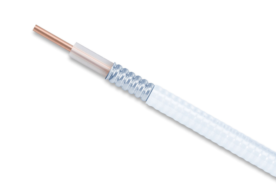
AL4RPV-50, HELIAX® Plenum Rated Air Dielectric Coaxial Cable, corrugated aluminum, 1/2 in, off white PVC jacket.
Features and Benefits
- This product is part of the ANDREW Wired for Wireless® Solution
Specifications
Product Classification
| Product Type | Air coaxial cable |
| Product Brand | HELIAX® |
| Product Series | AL4-50 |
| Ordering Note | ANDREW® standard product (Global) |
General Specifications
| Flexibility | Standard |
| Jacket Color | Off-white |
| Performance Note | Attenuation values typical, guaranteed within 5% |
Dimensions
| Diameter Over Jacket | 15.748 mm | 0.62 in |
| Inner Conductor OD | 4.572 mm | 0.18 in |
| Outer Conductor OD | 14.046 mm | 0.553 in |
| Nominal Size | 1/2 in |
Electrical Specifications
| Cable Impedance | 50 ohm ±2 ohm |
| Capacitance | 75.459 pF/m | 23 pF/ft |
| dc Resistance, Inner Conductor | 1.575 ohms/km | 0.48 ohms/kft |
| dc Resistance, Outer Conductor | 1.575 ohms/km | 0.48 ohms/kft |
| dc Test Voltage | 4000 V |
| Inductance | 0.19 µH/m | 0.058 µH/ft |
| Insulation Resistance | 100000 MOhms-km |
| Jacket Spark Test Voltage (rms) | 5000 V |
| Operating Frequency Band | 1 – 6000 MHz |
| Peak Power | 40 kW |
| Power Attenuation | 2.325000047683716 |
| Pulse Reflection | 0.5% |
| Velocity | 88 % |
Attenuation
Attenuation
| Frequency | Attenuation (dB/100 m) | Attenuation (dB/100 ft) | Average Power (kW) |
| 1.0 MHz | 0.216 | 0.066 | 35.37 |
| 1.5 MHz | 0.264 | 0.081 | 28.84 |
| 2.0 MHz | 0.306 | 0.093 | 24.95 |
| 10.0 MHz | 0.691 | 0.211 | 11.04 |
| 20.0 MHz | 0.985 | 0.300 | 7.75 |
| 30.0 MHz | 1.213 | 0.370 | 6.29 |
| 50.0 MHz | 1.581 | 0.482 | 4.83 |
| 85.0 MHz | 2.087 | 0.636 | 3.66 |
| 88.0 MHz | 2.126 | 0.648 | 3.59 |
| 100.0 MHz | 2.274 | 0.693 | 3.35 |
| 108.0 MHz | 2.368 | 0.722 | 3.22 |
| 150.0 MHz | 2.821 | 0.860 | 2.70 |
| 174.0 MHz | 3.054 | 0.931 | 2.50 |
| 200.0 MHz | 3.292 | 1.003 | 2.32 |
| 204.0 MHz | 3.327 | 1.014 | 2.29 |
| 300.0 MHz | 4.104 | 1.251 | 1.86 |
| 400.0 MHz | 4.808 | 1.465 | 1.59 |
| 450.0 MHz | 5.134 | 1.565 | 1.49 |
| 460.0 MHz | 5.197 | 1.584 | 1.47 |
| 500.0 MHz | 5.445 | 1.659 | 1.40 |
| 512.0 MHz | 5.517 | 1.682 | 1.38 |
| 600.0 MHz | 6.032 | 1.839 | 1.26 |
| 700.0 MHz | 6.583 | 2.007 | 1.16 |
| 800.0 MHz | 7.105 | 2.166 | 1.07 |
| 824.0 MHz | 7.227 | 2.203 | 1.06 |
| 894.0 MHz | 7.574 | 2.308 | 1.01 |
| 960.0 MHz | 7.892 | 2.405 | 0.97 |
| 1000.0 MHz | 8.081 | 2.463 | 0.94 |
| 1218.0 MHz | 9.068 | 2.764 | 0.84 |
| 1250.0 MHz | 9.207 | 2.806 | 0.83 |
| 1500.0 MHz | 10.256 | 3.126 | 0.74 |
| 1700.0 MHz | 11.053 | 3.369 | 0.69 |
| 1794.0 MHz | 11.416 | 3.480 | 0.67 |
| 1800.0 MHz | 11.439 | 3.487 | 0.67 |
| 2000.0 MHz | 12.192 | 3.716 | 0.63 |
| 2100.0 MHz | 12.559 | 3.828 | 0.61 |
| 2200.0 MHz | 12.920 | 3.938 | 0.59 |
| 2300.0 MHz | 13.276 | 4.046 | 0.57 |
| 2500.0 MHz | 13.975 | 4.259 | 0.55 |
| 2700.0 MHz | 14.656 | 4.467 | 0.52 |
| 3000.0 MHz | 15.649 | 4.770 | 0.49 |
| 3400.0 MHz | 16.928 | 5.159 | 0.45 |
| 3600.0 MHz | 17.551 | 5.349 | 0.43 |
| 3700.0 MHz | 17.859 | 5.443 | 0.43 |
| 3800.0 MHz | 18.164 | 5.536 | 0.42 |
| 3900.0 MHz | 18.467 | 5.628 | 0.41 |
| 4000.0 MHz | 18.768 | 5.720 | 0.41 |
| 4100.0 MHz | 19.066 | 5.811 | 0.40 |
| 4200.0 MHz | 19.363 | 5.902 | 0.39 |
| 4300.0 MHz | 19.658 | 5.991 | 0.39 |
| 4400.0 MHz | 19.951 | 6.081 | 0.38 |
| 4500.0 MHz | 20.241 | 6.169 | 0.38 |
| 4600.0 MHz | 20.531 | 6.257 | 0.37 |
| 4700.0 MHz | 20.818 | 6.345 | 0.37 |
| 4800.0 MHz | 21.104 | 6.432 | 0.36 |
| 4900.0 MHz | 21.388 | 6.519 | 0.36 |
| 5000.0 MHz | 21.671 | 6.605 | 0.35 |
| 6000.0 MHz | 24.420 | 7.443 | 0.31 |
Return Loss/VSWR
| Frequency Band | VSWR | Return Loss (dB) |
| 450–680 MHz | 1.288 | 18.00 |
| 680–960 MHz | 1.135 | 24.00 |
| 1695–2200 MHz | 1.222 | 20.00 |
| 2300–2700 MHz | 1.288 | 18.00 |
| 3100–3300 MHz | 1.288 | 18.00 |
| 3300–4200 MHz | 1.377 | 16.00 |
| 5150–5925 MHz | 1.377 | 16.00 |
Material Specifications
| Dielectric Material | PE spline |
| Jacket Material | PVC |
| Inner Conductor Material | Copper-clad aluminum wire |
| Outer Conductor Material | Corrugated aluminum |
Mechanical Specifications
| Minimum Bend Radius, multiple Bends | 127 mm | 5 in |
| Minimum Bend Radius, Single Bend | 63.5 mm | 2.5 in |
| Number of Bends, minimum | 15 |
| Tensile Strength | 79 kg | 174.165 lb |
| Bending Moment | 6.779 N-m | 5 ft lb |
| Flat Plate Crush Strength | 1.429 kg/mm | 80 lb/in |
Environmental Specifications
| Installation temperature | -5 °C to +60 °C (+23 °F to +140 °F) |
| Operating Temperature | -20 °C to +85 °C (-4 °F to +185 °F) |
| Storage Temperature | -20 °C to +85 °C (-4 °F to +185 °F) |
| Attenuation, Ambient Temperature | 20 °C | 68 °F |
| Average Power, Ambient Temperature | 40 °C | 104 °F |
| Average Power, Inner Conductor Temperature | 100 °C | 212 °F |
| Fire Retardancy Test Method | NFPA 262/CATVP/CMP |
Packaging and Weights
| Cable weight | 0.208 kg/m | 0.14 lb/ft |
Documentation & Downloads
Certificate of Compliance
Product Specification
Video
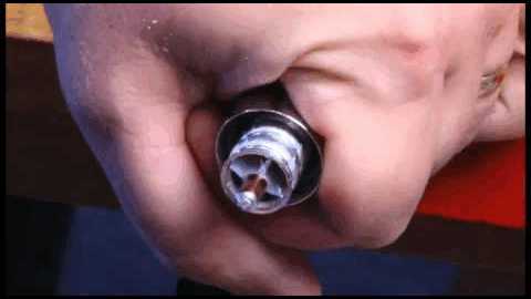
Positive Stop® Series Connectors Installation using a Manual Cable Preparaton Tool

Positive Stop® Series Connectors Installation using a Manual Cable Preparaton Tool

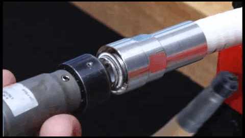
Positive Stop® Series Connectors Installation using an Automated Cable Preparaton Tool
Warranty
Certificate of Compliance
Product Compliance Documentation
Product Specification
Video
Positive Stop® Series Connectors Installation using a Manual Cable Preparaton Tool

Positive Stop® Series Connectors Installation using a Manual Cable Preparaton Tool

Positive Stop® Series Connectors Installation using an Automated Cable Preparaton Tool
Warranty
Other Ways to Browse


